The Hacking Port
The Hacking Port is a 2x8 pin header on the right side of the badge that exposes 6 spare GPIO pins, plus power and ground. Use it to add sensors, LEDs, buttons, or whatever you want.
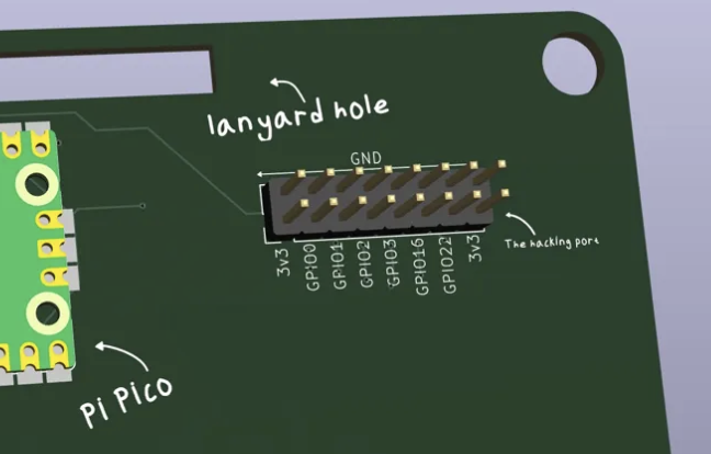
Pinout
    [1]  [2]
    3V3  GND

    [3]  [4]
    GP0  GND

    [5]  [6]
    GP1  GND

    [7]  [8]
    GP2  GND

    [9]  [10]
    GP3  GND

    [11] [12]
    GP6  GND

    [13] [14]
    GP7  GND

    [15] [16]
    3V3  GND
All pins are 3.3V logic. Don't feed 5V into these pins or you'll fry the Pico.
Examples
Add an LED
Wire an LED + 330 ohm resistor from GP0 to GND, then in MicroPython:
from machine import Pin
led = Pin(0, Pin.OUT)
led.on()
led.off()
Add a Button
Wire a button from GP1 to GND, then:
button = Pin(1, Pin.IN, Pin.PULL_UP)
if not button.value():
    print("button pressed")
Add a Sensor
Most digital sensors use SPI or I2C. The
Pico supports both. Check the sensor datasheet for wiring and use the machine module to communicate.
I2C and SPI
The Pico has two SPI busses and two I2C busses already in use by the display, but you can bit-bang additional ones using any GPIO pins.
For I2C on custom pins:
from machine import Pin, I2C
sda = Pin(0)
scl = Pin(1)
i2c = I2C(id=-1, sda=sda, scl=scl, freq=400000)
Power Limits
3V3 can source about 300mA total, shared with the Pico. If you're adding power-hungry stuff like motors or lots of LEDs, you'll need an external power supply.
GND is common across the entire badge. Safe to use for any external circuits.